This is the build guide for the older plinky kit, which you can identify because it has a GREEN mainboard. If your plinky has a BLUE mainboard, please check the newer build guide.
Build guide video
Thank you for the wonderful video, Roland & Enrica of Making Sound Machines.
Getting ready
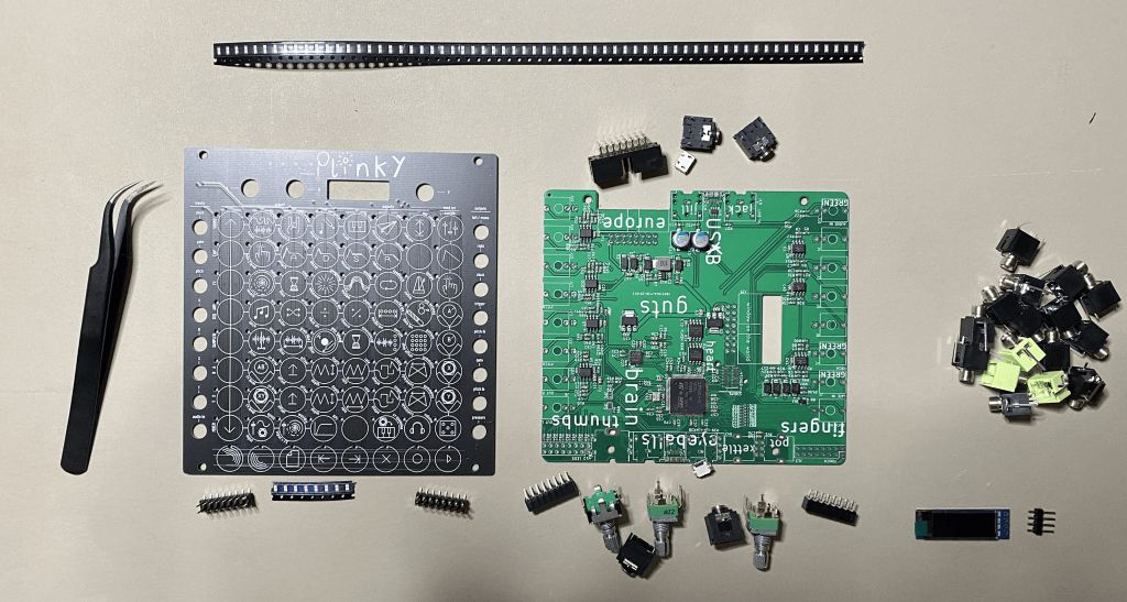
Congratulations on getting a Plinky kit! It’s a relatively easy build, with the most unusual bit being the surface mount LEDs - but don’t worry, you can do it!
Requirements
You will need:
- A soldering iron and solder
- Tweezers for the LEDs
- Side cutters or sharp wire cutters to trim some pins
- An hour or two of time.
If you want to calibrate the 1V/Octave output, you’ll need a multimeter or calibrated eurorack oscillator, and a eurorack patch cable. But the kit comes pre-CV-calibrated, so it’s not strictly necessary.
Let’s go!
Before you start
General safety
Safety first!
- REMEMBER TO TAKE CARE WITH A SOLDERING IRON, IT’S HOT!
- WEAR EYE PROTECTION WHEN CUTTING THINGS!
Soldering advise
Plinky is a relatively straightforward build, however a few people have slipped up so I thought I would write some general soldering tips here.
THE NUMBER ONE THING TO REMEMBER IS:DESOLDERING IS 100 TIMES HARDER THAN SOLDERING, AND NORMALLY DESTROYS THINGS.
Sogo slow! Take care! It’s easier to get it right first than it is to try to fix it. Think before you solder :) I say this from bitter experience. (RIP my befaco hexmix, sweet prince). And dont make the number 1 beginner mistake, which is to throw lots and lots and lots of solder at something. Trust me, I’ve been there. It makes things worse. It’s actually really hard to remove things once you’ve mis-soldered them. So Go Slow, and focus on making nice clean joints, not pouring huge amounts of solder on.
TOO MUCH SOLDER = SHORT CIRCUITS, BROKEN (FILLED UP) SOCKETS, BAD TIMES
IF YOU HAVENT SOLDERED BEFORE, PLEASE READ THE ADAFRUIT SOLDERING GUIDE BEFORE STARTING
https://learn.adafruit.com/adafruit-guide-excellent-soldering/
Plinky-specific gotchas
Ok now some Plinky specific things.
- DO NOT ADD LOADS OF SOLDER TO THE SOCKETS- (one of the first things you solder). They will happily suck up solder into the socket, blocking it full of solid metal! I don’t want to scare you - for most builds, this isnt a problem! But if you’re not aware, it can trip even the most experienced solderer up. This is almost impossible to remove without destroying your socket (at best) and your board (at worst). You only need enough solder to make a clean joint between the pin and the pad. Don’t be tempted to keep adding solder and keep adding - its gotta go somewhere! And where it goes is into the socket holes, blocking it up. Getting that sucker out after that happens is hard.
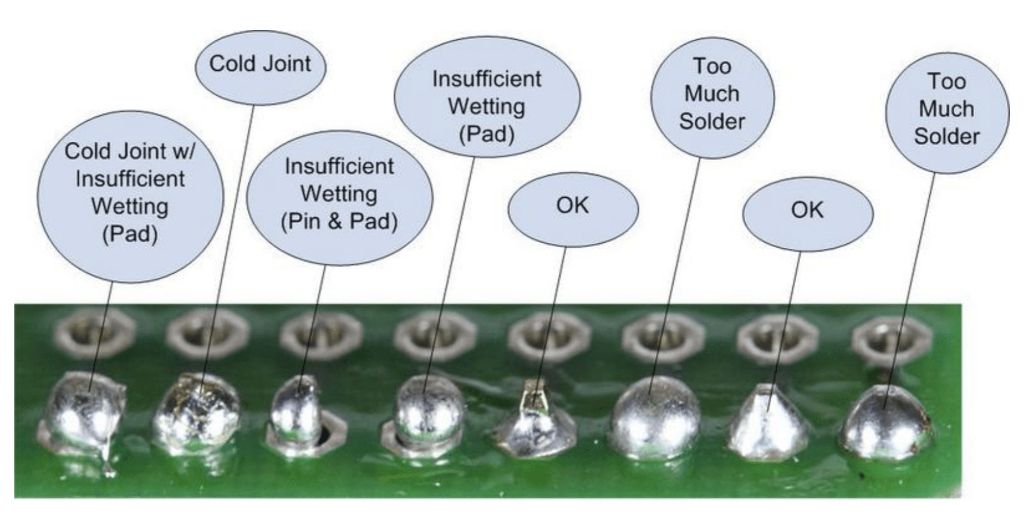
- In general, to solder you want to heat up the pad and the pin first with your iron, before adding any solder to it. If you can, use a temperature controlled iron at around 320 degrees C or more. Then, apply the solder - judiciously! - to the joint. Leave the heat there a second longer until the solder has formed a nice clean ‘tent’. Only a small amount of solder is needed per joint! More info in the adafruit guide above.
- Fixing a blobby joint - dont just add more and more solder, especially for the sockets. (see 1). ‘Reheat’ (aka reflow) what’s there already, maybe a dab of new solder to supply flux (or even better, add flux directly from a flux pen).
99% of all build problems with Plinky are NOT the LEDs, which everyone is scared of. It’s the sockets and pin headers! So please, take care over them. I’ll add a troubleshooting appendix at the end of this document. But Plinky generally works fine - most problems are a dodgy solder connection on the sockets or the pins that go into them. Plinky isn’t harmed by this! So it’s not the end of the world. But just know that it’s all about the sockets. :)
OK! Armed with our awesome soldering knowledge, let’s go!
Preparation
1. Remove the PCB assembly rails
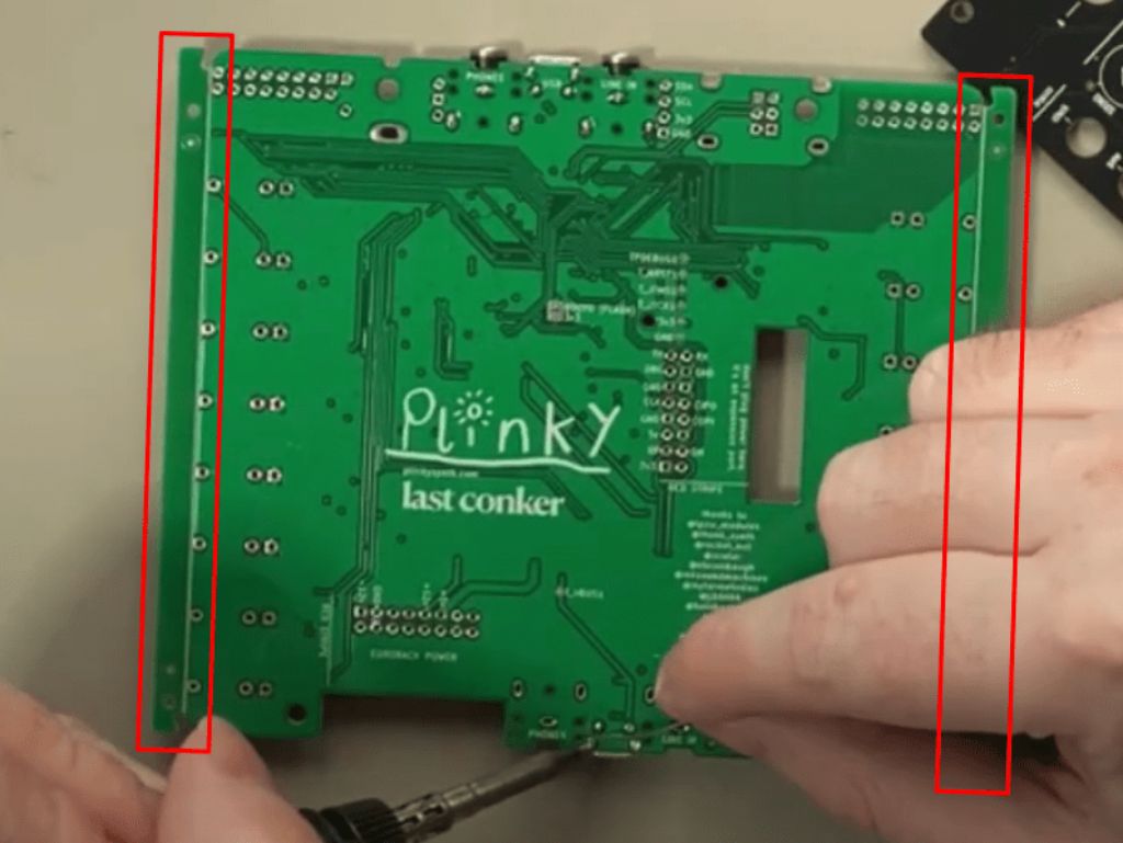
You may find that your board has two 5mm ‘rails’ on its left and/or right sides. These are a side effect of the manufacturing process, and are pre-scored to make them easy to remove. You should gently snap them off, if they are there. See 6:07 in this video to see what I mean - https://youtu.be/M9FH82lPIkM?t=367
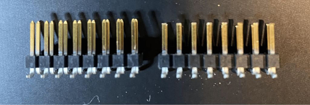
2. Trim the PCB headers
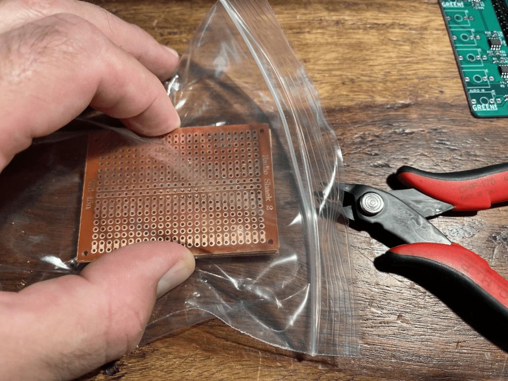
Now we need to trim about 1mm off all the pins of these 2x8 pin headers. They make’em a bit too long, sadly. WEAR EYE PROTECTION WHEN TRIMMING THE HEADERS! YOU DO NOT WANT THE TINY BITS OF OFFCUT METAL GOING IN YOUR EYES, OR ANYONE ELSE’S. Ron Millar from the Plinky discord suggests doing this step using the cutters inside a plastic bag to catch the offcuts! Clever!
Don’t trim more than 1mm off these pins. It’s better to trim too little than too much. Just the ‘tips’ is enough! Here’s a before and after picture - not much is snipped at all!
It’s good to keep it even. A good way to do it evenly is, to use the little green rails you snapped off the PCB earlier, as a guide. Place one between the pins of both headers, and trim the tips. This trick was invented by Plinky user OrangeTronic on the discord. Thanks!
Another way, that I have used - if you have old stripboard lying around, to stack 3 layers (1.6mm x 3) and poke them through - that leaves just the right amount poking through, to be cut flush with side cutters.
After you’ve trimmed them,remove any burrs or other bits of metal as best you can. If the ends of the pins are too bent out of shape or covered in broken burrs, they can break off in the socket and make a bad connection.Remember, these sockets and pin headers are the heart of Plinky’s UI and the thing that most people trip up on, so take your time.
Once you’ve trimmed the pins on the headers, turn them upside down and push them firmly but gently into the sockets you soldered.There’ll still be 1mm of bare metal visible between pin header insulation and socket - that’s fine.
Don’t push too hard. If you have to really force it, you’re gonna break the socket or the pins. Perhaps there’s a burr of metal blocking entry? Don’t use brute force - back off and clean things up then try again. The goal of the trimming is for the splayed legs on the pin sockets to end up at the right height to meet neatly with the front panel, at the same height as the other components (pots, sockets, etc).
Mainboard assembly
Solder the headphone & line-in ports

Start by placing & soldering in the stereo jack sockets. Make sure they are flush to the board before soldering them, especially if you have an aluminium or 3d printed case. They go in pairs either side of the USB ports, and there are 4 in total. The ones on the right are for headphones; the ones on the left are for line-in.
Some users reported that Plinky doesn’t fit in their eurorack case with both sets of sockets fitted. If you intend to use Plinky in a small euro case, see if Plinky fits OK before soldering these. Plinky will work fine without these jacks being soldered at all, or with just one pair soldered.
Secure the USB ports

Now solder the through-hole part of the 2 USB connectors, between the jacks that you just soldered. Plinky comes with the USB ports pre-mounted on the top side, but they also have pins that need soldering from the bottom to secure them firmly to the board. They don’t need a massive amount of solder - just make it secure by filling up the little holes with a wee bit of solder!
Inter-board connectors

Next, solder the 8x2 pin sockets at the top of the board, where it says ‘fingers’ and ‘thumbs’. Again, make sure they are flush when soldering. THESE ARE THE CAUSE OF MANY PEOPLES PROBLEMS. DO NOT OVER SOLDER THEM, THEY FILL UP! Just apply a normal amount of solder, and make sure your joints are nice and clean. Because they seem so innocuous and simple, people rush. Don’t rush! These babies are the key to all the lights and touch controls of Plinky, so put on some nice relaxing music and take it nice and slow. Channel your greatest soldering hero. And Don’t overdo the solder :)
Tip: To get these flush to the board, solder the diagonal pins first. Then inspect, and if they aren’t flush, hold the connector and board with 1 hand and your soldering iron with the other and reheat the joints. It will click into place!
Eurorack power (optional if you will not use Plinky in a rack)

The eurorack power connector goes into the board where it says ‘europe’. Don’t put it in the footprint next to the hole - that’s for a future expansion and can be left unpopulated. Now, solder away!
Solder the OLED screen

Now take the 4 pins for the OLED screen, and slide the little plastic insulation up a tiny bit with your fingers so that when placed into the OLED board, the pins JUST go through the hole, and are flush on the topside.

We want to maximise the length of pins under the display. Solder them in place into the OLED, from the top side. Again, make sure they are flush and perpendicular to the display.
Place the sockets and pots

Now place the two pots and encoder in between the pin headers, and black & green eurorack jack sockets down the sides. BUT DO NOT SOLDER THEM YET!
Do the 2 pots (knob with dark green body) first as they are the trickiest to place; you may need to squidge the outer (fat) legs in a little to make them fit; be gentle as the 3 pins may bend easily if you don’t line them up with the holes. Next place the encoder (the remaining knob that clicks when you rotate its knob) in the body; one of the outer legs will hang off the side.
Take care to place the 3 light green jack sockets in the right spots, marked ‘GREEN!’. The other 13 are black.
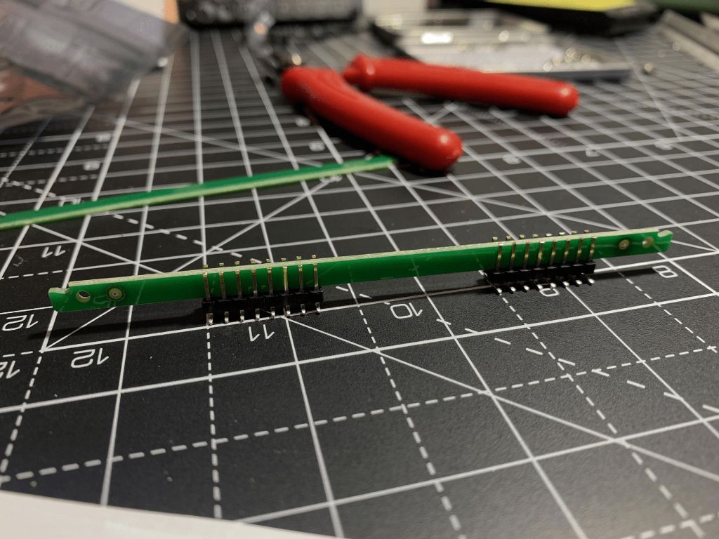
Lastly, loosely slot the display into its position so that it sits on top of the headphone jacks and usb socket at the top of the board. At this point, your main board should look like the picture on the left, with the sockets, display and other elements still ‘loose’:


Now place the front panel over all the pots and jack sockets, so that everything is lined up, as in the picture on the right. If you want, screw a couple of the nuts onto the jack sockets to hold things in place.

Carefully turn it all upside down and balance it on something (like the little plastic box in the pic above) so that it’s kept a tight sandwich while you are soldering everything from the underside.It’s important everything is as tightly sandwiched as possible, so that it fits into the case. I also like to pull the encoder (rightmost knob) a little out from the board, to equalise its shaft length with the two pots as much as possible. Although it works flush too, I recommend pulling it out as far as you can while still leaving enough of the pins to solder from the bottom side. Don’t worry about soldering the encoder’s outer leg (the one hanging over the side) - it’s okay to dangle there unsoldered.
Solder the display last, making sure that it is at a nice square angle lined up with the front panel’s hole, and flush with the front panel. Its 4 pins will only just make it through the holes on the green main board. Once it’s perfect, solder them!
While you still have everything sandwiched together, the last thing to solder are the splayed pin headers that should be just touching the front panel, like this:

It’s a bit fiddly, but by doing it this way, you can be sure it all lines up nicely. Check the sandwich is tight - if the pins are holding the board and front panel too far apart, it means you didn’t trim enough off the pins in the earlier step. If the pins are floating off the front panel, pull them out of the sockets slightly until they are flush with the front panel.
You’ll only be able to solder the visible 8 pins on each side - there are 8 more on the ‘inside’ of the sandwich, but we’ll do them next.
Finishing the connectors on the front panel

You’ll need to prise the front panel of your newly soldered Plinky apart - do this carefully and gradually, the pins are quite stiff. I work it slowly bit by bit, alternating both sides.
Now you can solder the remaining pins on the inside of the front panel - 8 on each side.
Now go and check your pin headers and sockets again! They are the heart of Plinky! On this front board side and the back side. Again, 99% of issues with the Plinky build come from bad joints with these pin headers or their sockets. Triple check your soldering, and reflow any joints that look dodgy. If you have a multimeter and know how to use its continuity mode, check with Plinky sandwiched together that the solder blobs you made on the bottom board can connect to the splayed pins on the top of the board. On the left header (viewed from the top), there should be no shorts between any pins. The right pin header is harder to check for shorts, as there are LEDs between most pin pairs.
Well done!
CONGRATULATIONS! Have a cup of tea, and give yourself a pat on the back, you have completed the main board. All that remains are the LEDs.
LEDs
1. Prepare the LED pads

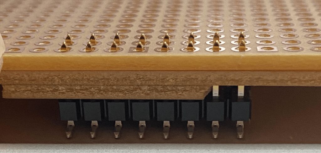
The first thing to do is prepare the front panel board with solder. If you have a reflow oven or a hot air gun, you can do this all using those tools, but the rest of this guide assumes just a normal soldering iron, and a pair of tweezers. First, put a tiny blob of solder onto one pad of each of the 72 LED footprints. I do the top pad of each pair (just above each hole) and the left pad of the bottom row.

You don’t need a lot of solder - just a tiny blob. It should look like little pillows of solder - like this - when you’re done.
The LEDs come packaged in little strips - there are 8 blue ones for the bottom row, and 64 white ones for the top. If you want to substitute your own colours, go ahead! You’re looking for 1204 to 1206 sized reverse mount (aka ‘bottom entry’) LEDs.
The ones I used are https://www.digikey.co.uk/product-detail/en/inolux/IN-S124ARUW/1830-1119-1-ND/7604662 for the white, and https://www.digikey.co.uk/product-detail/en/inolux/IN-S124ARB/1830-1117-1-ND/7604658 for the blue - though they are available in different colours and from different suppliers.

Let’s do the 8 blue ones first. Carefully pull off the clear plastic cover, and empty them into a dish or a clear bit of your desk.**WATCH OUT they are super easy to lose as they weigh next to nothing. TAKE CARE!!**If you lose them & need more, you’ll have to order some from digikey or mouser or other electronics supplier (links above).
Using tweezers, plop the blue LEDs into the holes along the bottom row (the ‘horizontal’ ones, marked D65-D72). MAKE SURE THE LITTLE GREEN PIXEL ART TRIANGLE ON THE LEDS IS VISIBLE, AND POINTING IN THE SAME DIRECTION AS THE TRIANGLES ON THE SILK SCREEN.
The little plastic lens of the LED sits inside the pre-drilled holes, which really helps to line it up. It should look like this:

Now, with your tweezers in one hand, press gently with the tweezers onto an LED, in the middle (where the green triangle is), and with your other hand touch the soldering iron onto the metal pillow of solder. The solder should melt, and the LED will ‘click’ down flat to the board. Repeat 8 times. Congratulations, you’ve soldered one side of the first 8 LEDs! It should look like this:

Now, using a small amount of solder with your iron, solder the ‘free’ end of each LED down. Thin solder helps, but if you have thick solder just wipe any excess off your iron as needed. It doesn’t matter too much if they aren’t perfectly straight, so long as both ends of each LED are cleanly soldered, and you got the green triangles lined up right with the white triangles marked on the board:

2. Solder the rest of the owl
CONGRATULATIONS! You are now an SMD soldering expert. Now all that remains is to repeat these steps for the 64 white LEDs. I’ve packed them as two strips of 33 - so you have two spare. TAKE CARE OF ORIENTATION! It’s much harder to unsolder than it is to solder - so double check.The 8 columns of 8 LEDs alternate in direction, so triple check again: the pixel art green arrow should match the triangles on the board silkscreen. It takes around half an hour to do them all, so put some music on and chill.
_Done? _YOUR Plinky IS NEARLY READY! Now you just need to squish the sandwich back together, screw on the hex nuts to secure it in place, and add the 3 knobs.
Please don’t over tighten the hex nuts on the sockets. There are thin copper wires which run along the board under the black insulation. With finger-tightness there is no issue. But if you use a strong driver to tighten the nuts, you may squish the circuit, scraping away the black coating and cause short circuits leading to problems.
Making the case
If you want, you can use 4 M3x15mm hex spacers, along with the 8 included M3 bolts, to hold Plinky together into a nice ‘pocket operator’ style ‘open case’. Screw the spacers into the base plate using M3 bolts, and then screw Plinky into them from above.

Take a moment to appreciate the majesty of your crafting skills.

You can also purchase a custom-made aluminium case from thonk. It is SO nice, but not required. :)
Congratulations! The hardware part is done! Now all that’s left is software & calibration!
Update and test
Let’s get the latest software onto Plinky. I STRONGLY RECOMMEND THIS STEP. In the presence of soldering errors, the latest firmware (version 0.9 and up) is better able to self-diagnose, whereas the original firmware (0.7) tends to just lock up if there are soldering errors.
1. Install the firmware
With Plinky powered off, hold down the encoder (the rightmost knob, with a clicky button in it) and while still held down, plug it into a PC or MAC USB port. The screen should remain blank - if it says ‘Calibration’, you’ve not held the knob down. Unplug and re-plug, trying again. If you’ve got it right, you’ll see a ‘tunnel’ of flashing lights on the main board. You can see it at the 46 minute mark here: https://youtu.be/M9FH82lPIkM?t=2759 Check that every light is working - if not, you may need to touch up your soldering. If nothing at all happens, unplug and go back and check absolutely everything for shorts or bad joints. If all else fails, it might be a software issue - see the section ‘Help my Plinky is dead!’ below.
Right so you’ve got flashing lights! That’s great. This is Plinky’s special ‘USB upgrade’ mode. Your PC should have made a little noise indicating that a new device is plugged in, and it should show up as a USB Drive.
If Plinky lights up with the tunnel of lights, but does NOT show up as a USB device on your PC, check your cable. It’s always the cable. Unfortunately, USB cables are a mess. Many are ‘power only’. Plinky needs a cable with 4 wires in it, to carry data. It should be a cable that you can use to transfer data with your phone or other device, for example. Typically, they are slightly fatter and less flexible than the really cheap ‘charging only’ cables. A few people reported raiding their cable boxes for 4 or 5 cables before they found a data cable! Playstation 4 controllers dont use data - they always use bluetooth, even when plugged in. So many playstation controller cables are charging only, and are thus no good.
OK Plinky’s turned up as a USB drive. Great! Drag and drop the latest firmware file (which should have extension .UF2) (which you can download from the firmware page) onto the Plinky USB ‘drive’. The lights will flicker, and that’s all there is to it! Your Plinky now has the latest software. Click the encoder to finish the upgrade process.
2. Touch calibration
The first time Plinky boots ‘normally’, or after you finish flashing it with the latest software, it will go into touch calibration mode_, _indicated on the display and by the bottom row of LEDs lighting up. You can watch me do this calibration process here - https://youtu.be/M9FH82lPIkM?t=2852
If nothing happens at all, don’t panic! Power down, check your soldering carefully for shorts, and if it still does nothing, it may just be a software issue. Skip to the ‘help my Plinky is dead’ appendix at the end of this document, and then come back here when it’s working.

In calibration mode, one LED in each column will be lit. Press your finger ‘evenly’ and as centrally as possible on one of the lit pads, ‘mezzo-forte’ (medium hard) for a few seconds. After a few seconds, it will start blinking and you can release. If you aren’t quite central with your finger, don’t release - just slide your finger into place with it held down, and keep it held down a few seconds once it’s central. If you completely mess up, just switch Plinky off and on again, and try again.
Plinky will ask you to do this for all 72 pads, by lighting them in turn. It takes a few minutes, but you only need to do it once. If you place Plinky in a new case, or you find that it is responding ‘offset’ to your finger presses, you may want to recalibrate by twisting the leftmost knob as Plinky powers up, to repeat this process.
Once you’ve finished, your Plinky is ready to play!
If you have firmware 0.9 or later (you should have put it on in the previous step!), calibration will tell you if it thinks there is a short or ‘no connection’ in your pin headers. If this happens, it will make the screen go white and tell you which column you are on where it thinks there is a problem. Take a note of which columns are problematic (counting 1,2,3 ...8 from the left to the right) but keep going with calibration. Then consult the troubleshooting appendix below for help.
If you left the firmware at the original version (0.7), if there are soldering issues with your pin headers, it may lock up. You’ll see ‘Calibration’ on the screen, but no pads will be lit, and you can’t calibrate. That’s a sign of a left-connector soldering issue. If you install new firmware, it will help you narrow things down; or just check all your soldering again on the top left connector.
CONGRATULATIONS! ITS DONE! HAPPY PLINKING!
Detailed instructions and videos can be found at the play guide.
Enjoy!
IF YOU HAVE PROBLEMS WITH PLINKY HAVING UNLIT LEDS, STUCK LEDS, OR NOT REGISTERING TOUCHES CORRECTLY, PLEASE CHECK THE TROUBLESHOOTING APPENDIX BELOW
Appendix
1. Common hardware issues
So, your Plinky booted up. You probably managed to put new firmware on it, even calibrate it, but during calibration it complained about some of the pads, or now that it’s running, you’ve noticed some LEDs are out or the touch is behaving weird. Don’t worry! These are the most common problems, and they’re easy to fix.
Here are some common problems
Q: Plinky always boots either to ‘calibration’ or play mode, but I can’t get it to boot into the ‘USB update’ mode (by holding down the encoder on boot)
A: check the solder joints around the encoder. Reflow them, and try again. Be sure to hold the encoder firmly down as you power Plinky up.
Q: Plinky doesnt show up on my PC as USB device when I boot in ‘update mode’. I can see the tunnel of lights, but no USB device shows up.
A: Check your cable. It’s always the cable. Unfortunately, USB cables are a mess. Many are ‘power only’. Plinky needs a cable with 4 wires in it, to carry data. It should be a cable that you can use to transfer data with your phone or other device, for example. Typically, they are slightly fatter and less flexible than the really cheap ‘charging only’ cables. A few people reported raiding their cable boxes for 4 or 5 cables before they found a data cable! Playstation 4 controllers don't use data - they always use bluetooth, even when plugged in. So many playstation controller cables are charging only, and are thus no good.
Q: One or two LEDs are unlit.
A: No sweat! Take a note of which LEDs, remove the front panel, turn it over, and check your soldering. Reflow joints of the problematic LEDs (with a bit of flux if you have it). Check the LED orientation. If the LED still doesn’t light after a couple of tries, it may be dead, though this is much more rare than a dodgy joint. Your kit came with 2 spare white LEDs, so you could always try replacing the LED.
Q: A whole row of LEDs is unlit.
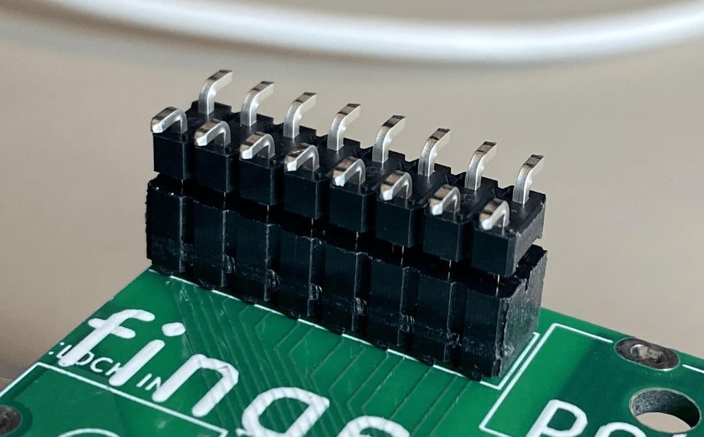
A: Don’t panic! You’ve just got a single dodgy joint on one of the pins of the connectors that go between the front and back panel. Looking at Plinky with xray eyes from the top (as if you’re playing it), there are two sets of 8x2 pins - one top left, the other top right. The LEDs are on the top right header. The rows of LEDs are controlled by the 8 pins that are on the ‘bottom’ row, as you look at it from above. In other words, the 8 pins further from the top of the board, on the right side connector. The first pin, on the left, is the first row of leds. Each pin to the right, corresponds to a row of LEDs going down the panel. So if the 6th row down of LEDs is out, you have a dodgy joint on the 6th pin from the left, on the bottom row, of the right connector. Go check the pin, on the front panel (bearing in mind that when you flip it over, left and right are swapped!), and on the back of the mainboard. Check if the socket itself is not damaged. For reference, the pinout of the right connector is:

The first 5 pins at the top correspond to columns of LEDs. The top right 2 pins, marked TS2_ and TS1_, correspond to the touch strip with blue LEDs at the bottom of Plinky. And the bottom 8 pins, from left to right, correspond to the LED rows, from top to bottom, as described in the paragraph above.
Bottom line: Row of LED’s out? Check your lower pins on the right connector.
Q: A whole column (or several) of LEDs is unlit
A: Same story as the previous answer - but its one of the top left 5 pins on the right connector, as you look at Plinky from above. Check your joints on both front panel board and the main board, and try again.
Q: Some LEDs are ‘stuck on’
A: You’ve got a short somewhere. Check for excessive solder blobs, or ‘bridges’, or places where two pins have become joined together in your sockets and connectors. Look out, if you put loads of solder on, it can wick under the insulation and make it tricky to see the short. Reflow the joints and poke under the insulation if the short refuses to go. If you have a multimeter, check for dead shorts between pins.
Q: Touch in a particular column is behaving weirdly, perhaps always registering the highest pad, or the lowest, or jumping from one end to the other wildly. Also, calibration probably complained about that column
Same story as the LEDs above, but with the LEFT connector. The left connector is all about the main 64 pads touch interface. It is 8 pairs of pins, left to right corresponding to the vertical columns of touch, also left to right. So if the 3rd row from the left is playing up, and doesn’t respond to touch, you’ve got a broken joint or a short circuit on the 3rd pair of pins from the left. Go check your soldering.
After you’ve fixed a touch issue, you’ll need to force Plinky to recalibrate. When you power it up, immediately twist the A knob. This will force Plinky into calibration. It will tell you if it’s happy or sad about particular rows.
Q: Touch in the bottom strip (with blue LEDs) is responding weirdly. Also, calibration probably complained about it (column 9)
See the answer to the previous question, however the pins in question are the two rightmost pins in the top row on the RIGHT pin header, looking at Plinky from the top. After fixing, you will need to recalibrate as above.
Q: I have more questions! I need more help!
A: Join our dedicated Discord server - it’s very friendly and we can help with any build issues you may encounter. https://discord.gg/Zf6chA9jAz
2. CV calibration (optional)
If you’re using your Plinky with other eurorack modules, the pitch inputs and outputs should be ‘factory’ calibrated for 1V / Octave. If you find that it is not tracking correctly across multiple octaves, you can recalibrate the pitch CV jacks using the following procedure. You will need a eurorack cable and either a voltmeter, multimeter, or calibrated eurorack oscillator.
As you power up Plinky, twist the B knob. Plinky will now go into CV calibration mode. Instructions will scroll across the display.
Plug one end of a eurorack cable into the ‘pitch lo’ output on the right side. Clip a voltmeter to the other end - black to the long metal bit of the jack plug, and red to the tip of the plug. Alternatively, you can plug it into a calibrated eurorack oscillator’s Volt/Octave input and use your ears.
Slide your finger up and down on theleftmostcolumn of Plinky, it should cause the voltage (pitch) to go slowly up or down. Adjust it until it is as close to 0v as you can get it (or until it sounds like C0 on your oscillator).
Now touch the second column of Plinky, and it should jump two octaves up - to 2v (C2 on oscillator). Adjust with your finger until it is as close as possible to 2v. You can alternate between the two octaves by pressing the first and second column. Once you are happy it’s a 2 octave gap (2v on the multimeter), move the cable to the pitch hi output on the right, and repeat the 0v and 2v calibration, this time using your finger on the3rdand4thcolumns of Plinky to set the voltages. (1st and 2nd still do ‘pitch lo’, so you can go back any time - just remember to move the cable to the correct output)
Once you’re happy, unplug the cable at the multimeter/oscillator end, and plug it into the ‘pitch in’ socket on the left, forming a loop-back.
Plinky should say ‘Just a mo…!’ while it self-calibrates its pitch CV input, and then it will finally ask you to unplug the cable. Once you’ve done that, it will start up in the ‘normal’ play mode! Calibration is done!
3. Recovering from a badly flashed or 'bricked' Plinky
1. HELP! My Plinky is totally dead!
If your Plinky becomes corrupted or ‘bricked’, but there are no electrical faults, and it refuses to even go into the normal ‘flashing’ mode (accessed by holding down the encoder on boot) you can force the software to be completely replaced using ‘DFU’ (Device Firmware Update). This is an emergency procedure,you shouldn’t need to do this in normal operation.
You first need to install a DFU flashing program on your computer. I recommend ST Microelectronics’ ‘STM32 Cube Programmer’, as they are a somewhat reputable firm, they make the processor chip in Plinky, and their software runs on Mac Windows and Linux. Unfortunately it requires Java to be installed, but it will guide you through that installation process.
Get it for free here: https://www.st.com/en/development-tools/stm32cubeprog.html. (At the time of writing (October 2020), a mac user has reported that JDK 8u231 from october 2019 is the best one to use, and that other JDKs caused the programmer to crash. On Windows 10, the default JRE seems to work).
If you have existing USB DFU software, that should work too. If you have problems installing it, you’ll have to ask ST…
2. Forcing Plinky into DFU mode
Once the DFU software is installed on your computer, make sure Plinky is unplugged, remove it from its case, then turn it over, and bridge together the 2 little silver pads marked ‘BOOT0’ - using the tips of metal tweezers, a piece of wire, or any small metal object.

While they are connected, power up Plinky over USB.It can be quite tricky to reliably connect themwhile also powering it up, so it may take a few tries. But if you are successful, the PC should recognise a new USB DFU device. Once detected, you can remove the connection across the pads.
If you cannot get the PC to recognise the DFU device at all, there may be something electrically wrong. Check all your soldering carefully, check for shorts between power lines with a multimeter, and if that still doesn’t help, ask on the discord server, invite link is at the Community page.
Now, run the STM32 Cube Programmer software that you downloaded in the previous step.

When you run stm32cubeprogrammer, a large window should appear similar to the image here. If the blue box on the top right isn’t saying USB, click on that to change it to USB.
Then click the ‘open file’ tab, and select the latest Plinky firmware DFU file, available at https://www.plinkysynth.com/firmware.
Now you have the Plinky in DFU mode, the PC software you installed should be showing ‘USB1’ in the ‘Port’ drop down. Press the little ‘refresh’ button on the top right if the port shows ‘No DFU detected’. Once detected, it should show a USB Device with a Serial number, like the picture on the right:

Now click the green ‘Connect’ button, and then the blue Download button. Wait a few seconds, and it should program. Once it’s done, press Disconnect, and you can unplug your Plinky. Don’t rush. If you unplug mid-program, you may find that you have to repeat this whole process.