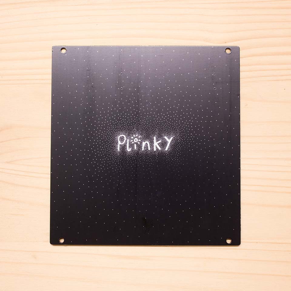
This is the build guide for the Plinky V3 kit from Thonk. It's easy to identify:
- black mainboard
- four stereo jacks at the bottom
- a single-line socket for the OLED screen at the top
Check out the old build guides if your Plinky has a green or blue mainboard.
Thank you for getting a Plinky kit. It is an easy DIY build suited for beginners and comes with many of the critical electronics pre-assembled. However, it does require very careful and precise soldering.
If this is your first time soldering, please read the Ifixit Guide to Soldering first.
Some tools you will need
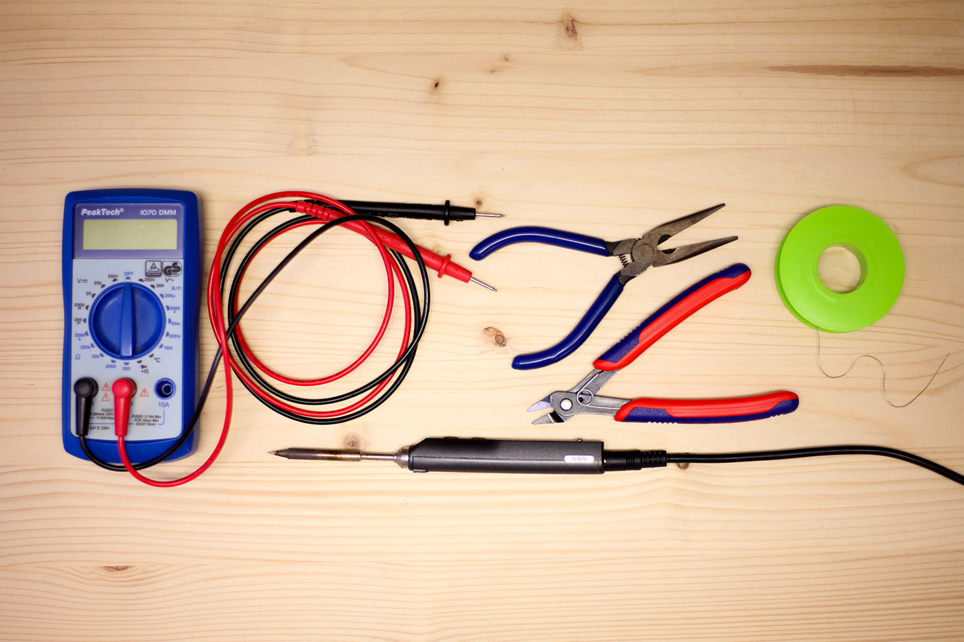
- A spool of solder. We use lead free 0.5mm.
- A soldering iron for electronics. A good temperature for soldering lead free solder is 375 - 380° C.
- Snipe-nose pliers
- A Multimeter
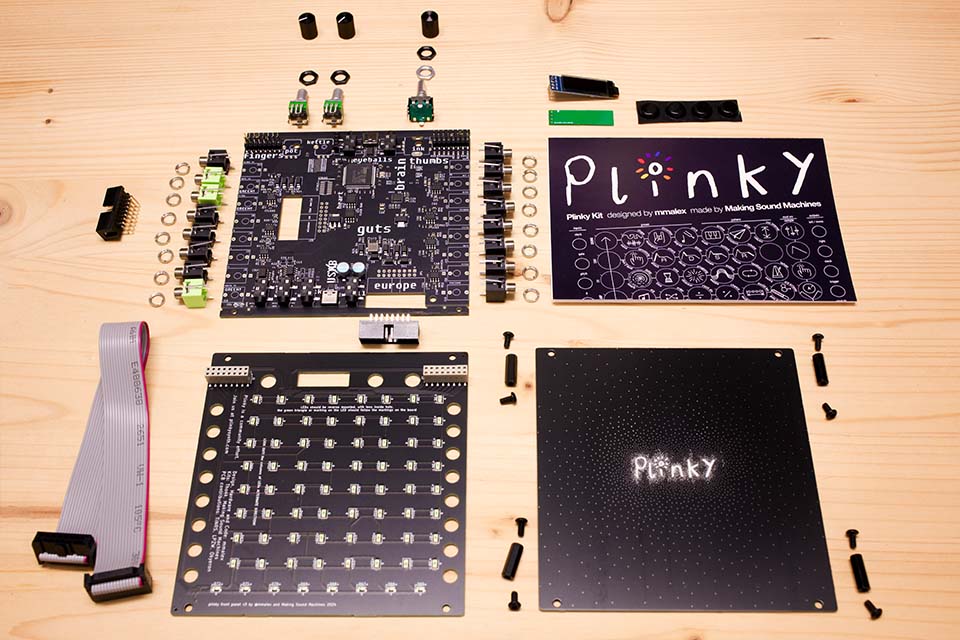
Here’s what you will find in the kit
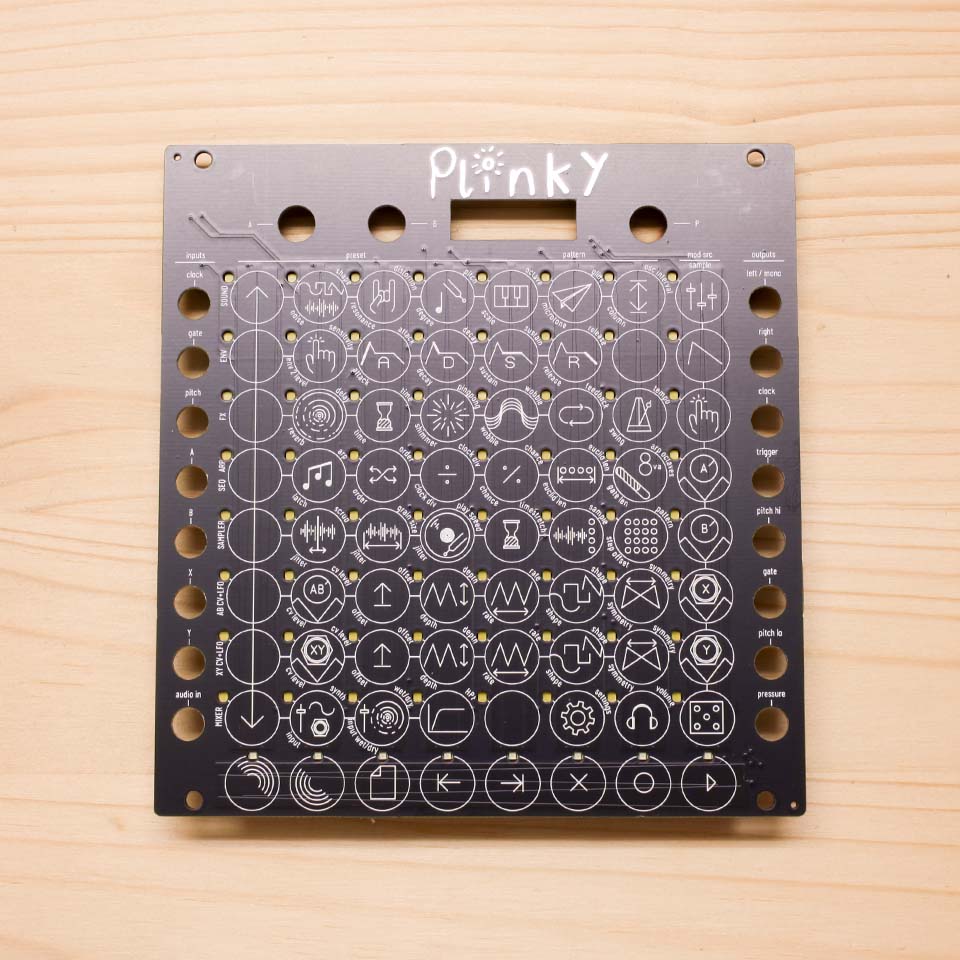
- The front panel
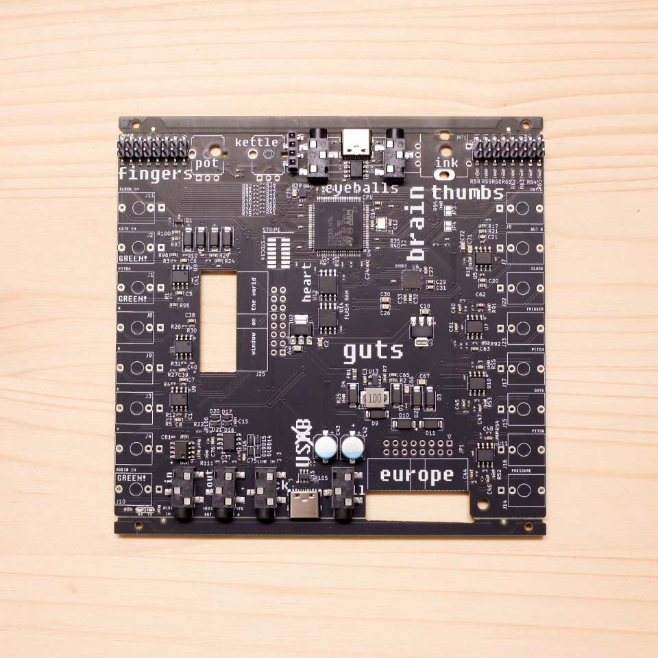
- The main board with presoldered components
- The back panel
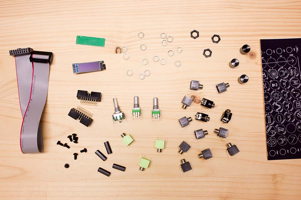
- Eurorack power cable
- OLED screen
- Green spacer PCB
- 2x 2x8 angled header
- 4x black hex standoffs
- 8x black M3 screws
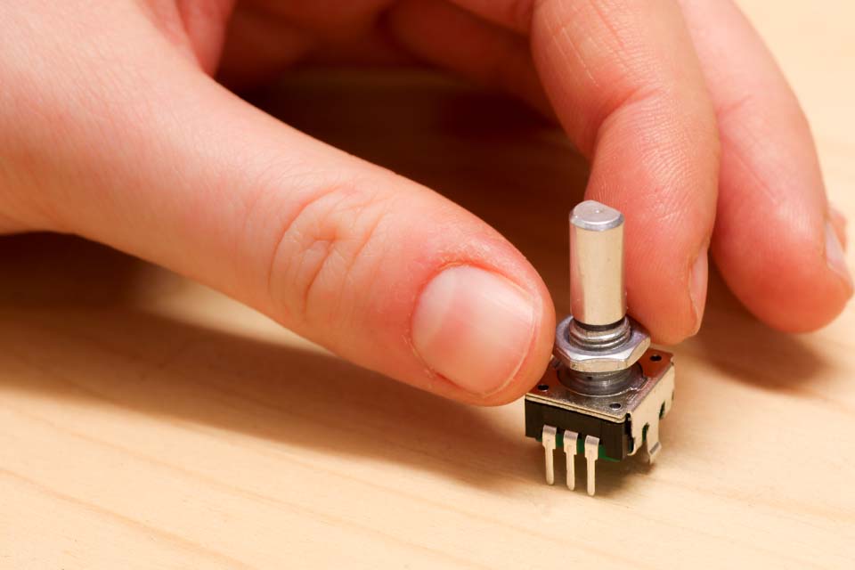
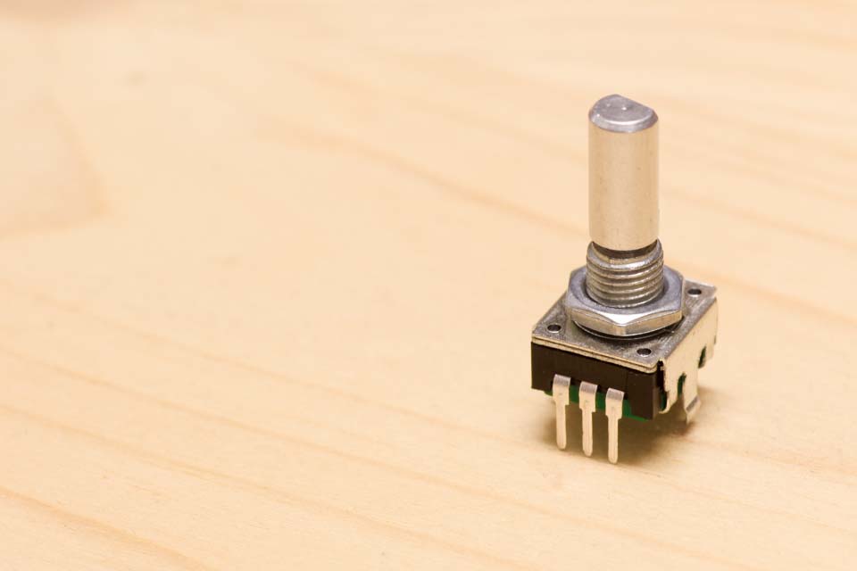
- 1x encoder + silver nut
- 2x potentiometers B10k
- 3x black hex nuts
- 1x encoder cap
- 2x potentiometer caps with indicator
- 13x black Thonkiconn
- 3x green Thonkiconn
- 16x knurled nuts
- 4x rubber feet
- Quickstart Guide
Please take a moment to find all 16x knurled nuts. They have a tendency to hide inside the Thonkiconn jacks - if you find you are missing any, most of the time they are just hidden inside the back of a Thonkiconn jack!
Build Guide
All of the SMD components on the PCB have already been assembled for you, so this is a very quick build. However, it does require very careful and precise soldering.
Avoid touching the SMD components with your hands and be very careful not to touch them with your soldering iron. Take your time, and use an iron with a reasonably small tip.
Remove the assembly rails
Your main board will come with 5mm rails at the top and bottom of the board. They are pre-scored to make them easy to remove. Hold the edge of the PCB in one hand, and use Snipe-nose pliers to pinch alongside the rail with your other. Gently bend the rail with the pliers until the rail snaps off.
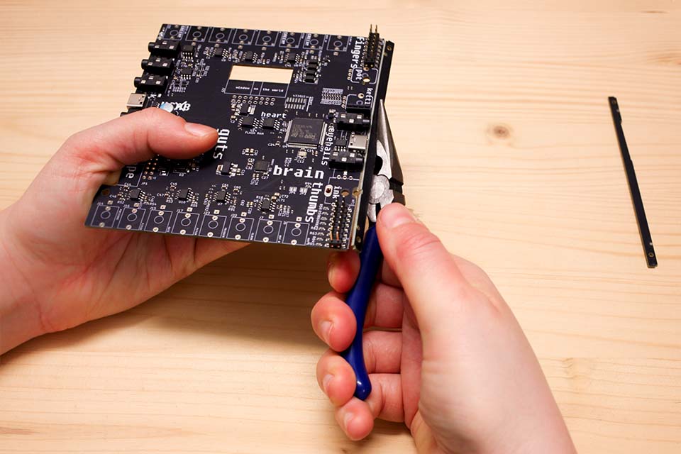
Snap off the 5mm rails at the top and bottom of the board.
2x8 Header
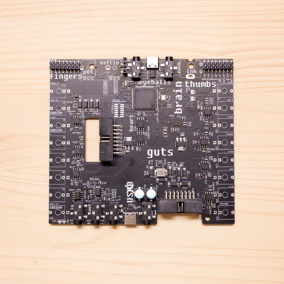
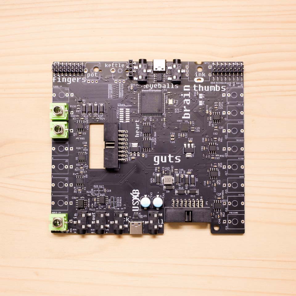
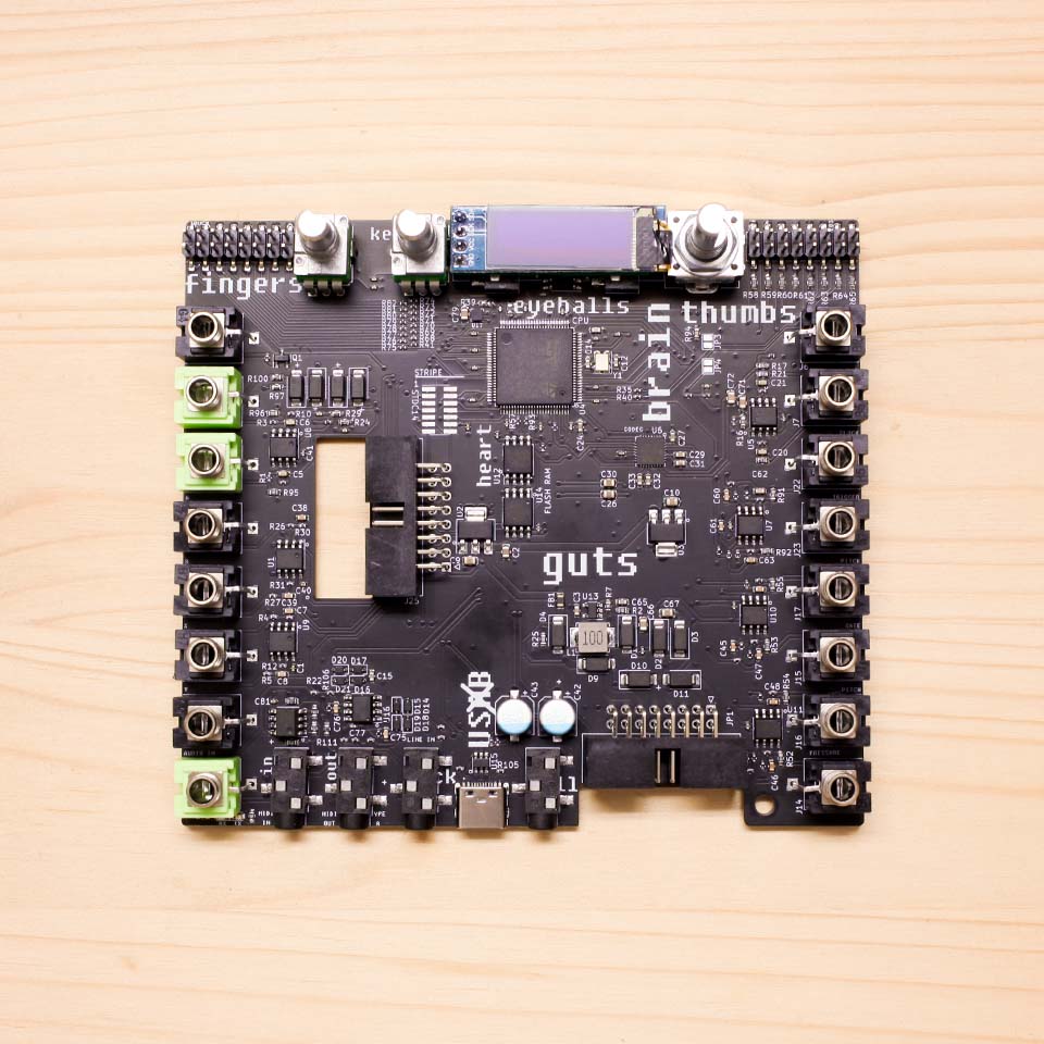
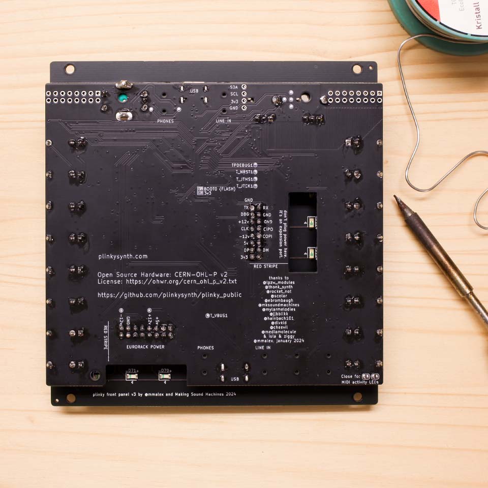
Turn the PCB over, so that the surface-mount components are facing up - this will be the front-facing side of Plinky. This side has the word ‘guts’ printed on it.
Start by placing the two 2x8 angled headers. The eurorack power connector goes into the board where it says ‘europe’. An identical part goes into the footprint for the expander that says ‘window to the world’.
The expander is an optional open-source 4HP Eurorack add-on to Plinky. Its most important feature, TRS Midi I/O, has been integrated into the design of Plinky V3 and can be found at the bottom of the main board. In addition to that, the expander provides front-panel access to USB and 4 CV sockets. Do not plug Euro power into the expander socket, it's for the expander only!
Make sure that the connectors sit on the correct side: the black plastic box should lay flush on the side that holds the SMD components. The short pins stick through the PCB and should be soldered on the bottom side.
Use a piece of masking tape to keep the headers in place, then flip the board over.
Using a fine soldering tip, solder one corner pin on each side first. Check that the pin header sits flush and reheat to adjust if necessary. Once the pin header sits flush, finish the two rows of pins on each header.
Potentiometers, Jacks and Screen
Next, orient the PCB so you can see the side with the SMD components. Place all the components onto the board, but do not solder anything yet.
The groups of rectangular outlines marked with J and a number indicate where to place the Thonkiconn jacks.
Place Green Thonkiconn
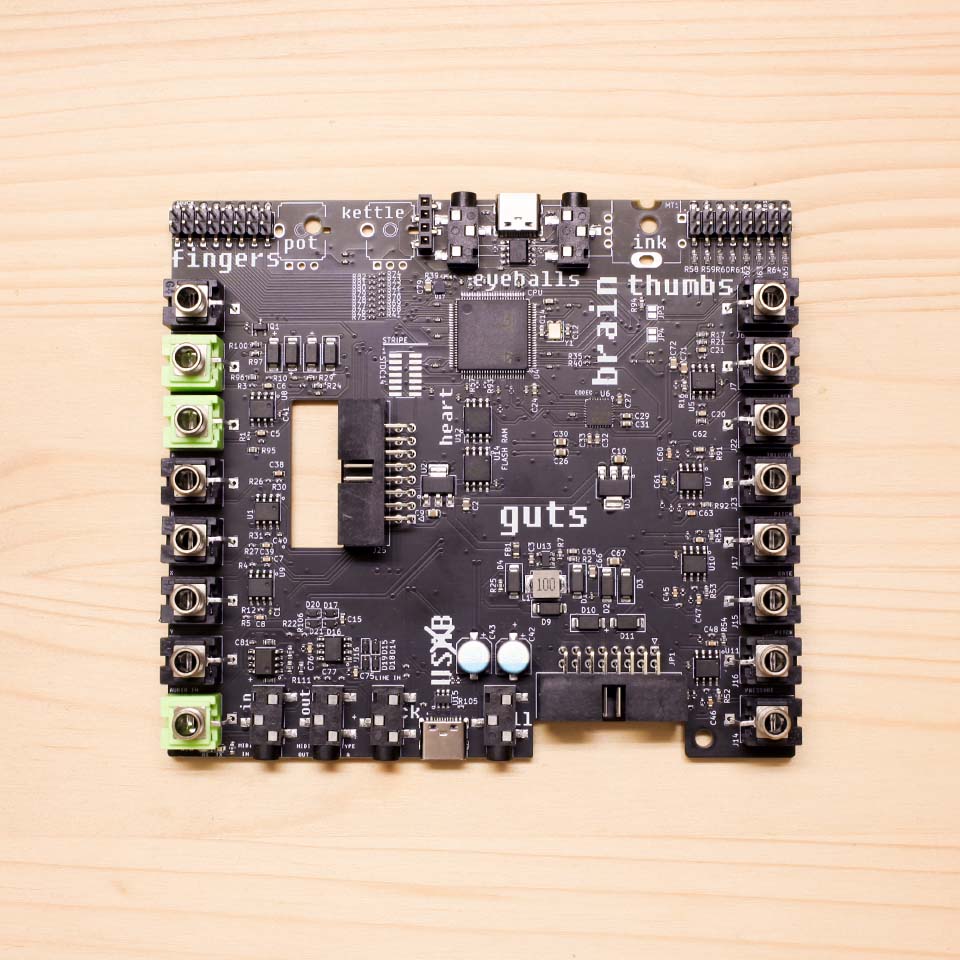
Place the three green Thonkiconn first. They go on the left hand side of the board, into the footprints marked GREEN!, and fill the second, third and last position from the top. Place but do not solder yet.
Place Black Thonkiconn
Fill the rest of the spots with black Thonkiconn, on the left and right hand side of the board. Place but do not solder yet.
Place Potentiometers and Encoder
Place the two potentiometers into the footprints marked ‘pot’ and ‘kettle’. Both potentiometers have three legs on one side and are marked B10k. Place but do not solder yet.
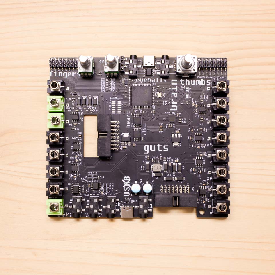
The encoder has a flatter housing than the potentiometers. You will find a hex nut in the kit. Screw it onto the encoder to offset the difference in height. Then place the encoder in the footprint that says ‘ink’.
With both the potentiometers and encoder, you may need to squidge the side brackets a little to make them fit. Be gentle as the pins may bend easily if you don’t line them up with the holes. Inspect to make sure all legs stick through the PCB, and the parts sit straight on top of the board.
Place the OLED screen
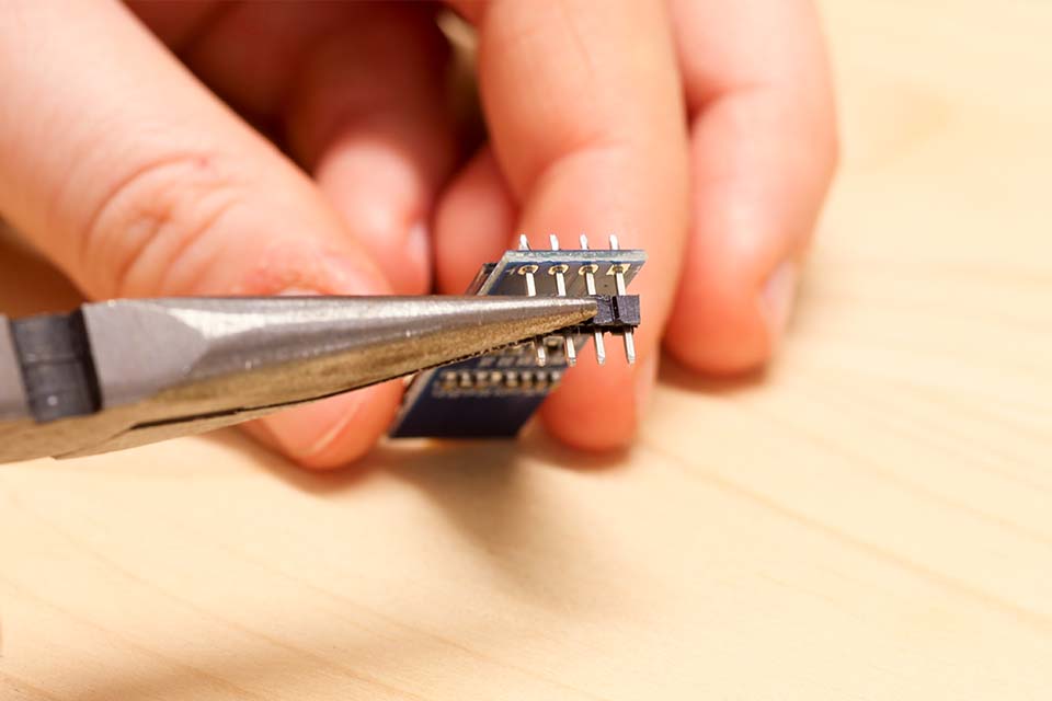
The OLED screen comes on a small blue PCB with the four-pin header presoldered.
In order to make it sit at the correct height, you need to carefully remove the black plastic from the legs with tweezers or pliers.
The screen is delicate. The OLED and glass is glued on, so the right way to hold it is at the blue PCB.
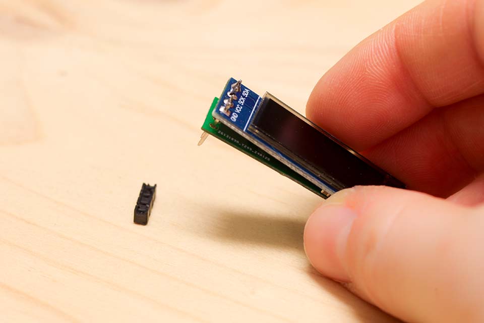
Make sure not scratch the glass surface.
Slide on the little green spacer PCB, so it sits under the blue PCB. The little white arrow is printed on the top side of the board, and points towards the SDA pin.
This PCB is to ensure no components on the underside of the OLED module accidentally make contact with the audio jacks.
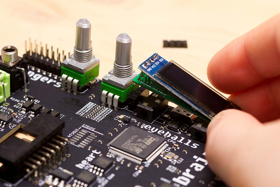
Gently slot the OLED into the single row socket - it should not require any force to do so.
Once placed correctly, the glass part should sit at the same height as the Thonkiconn and potentiometers.
Unlike on previous versions of Plinky, you do do not need to solder anything on the OLED screen. As it is held in place with a socket, it is also relatively easy to replace should it ever scratch or break.
The screen comes with the kind of protective film that prevents electronic devices from truly being your own. Now is the time to remove the protective film from the screen.
Place Panel + Thonkiconn Nuts
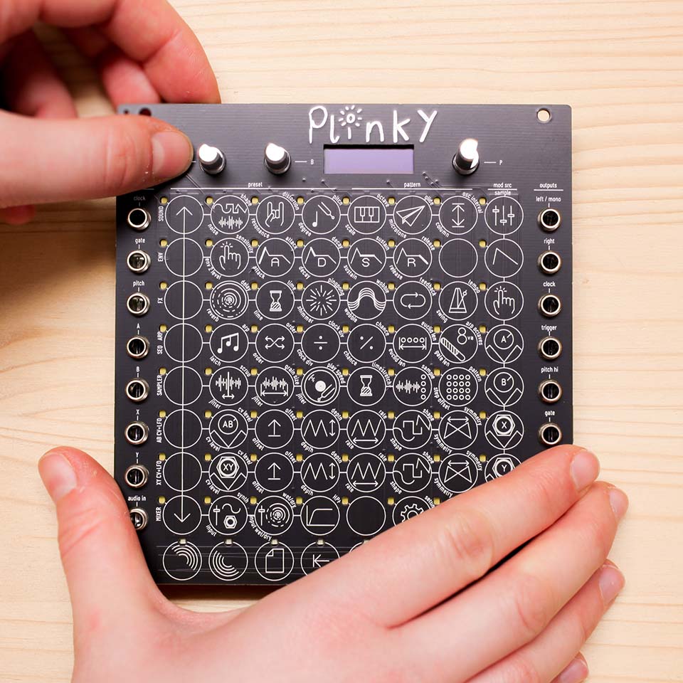
Once all the components are in place, but not soldered yet, make sure everything lines up and put on the front panel.
The front panel has two grey 2x8 sockets on its underside, which line up exactly with the two 2x8 pin headers on the main board.
Align the sockets and headers so that they match, and gently push the front panel onto the main board. If done correctly, the Thonkiconn jacks align with the holes so that their metal threads sticks through the panel.
Check that the screen sits right and is pushed down into its socket. The panel should sit flat and not flex. You can adjust your screen with tweezers to have it properly aligned with the panel cutout.
Screw on the knurled Thonkiconn nuts and the black hex nuts for potentiometers and encoder, so the panel sits tightly atop the jacks and pots, and the jacks sit flush on the PCB.
Solder Thonkiconn and Potentiometers
Before you solder, make sure everything is as tightly sandwiched as possible. Solder the jacks first, so the whole arrangement holds together. Check one last time everything sits right, then solder the potentiometer and encoder legs on the back.
Do not solder the four screen pins.
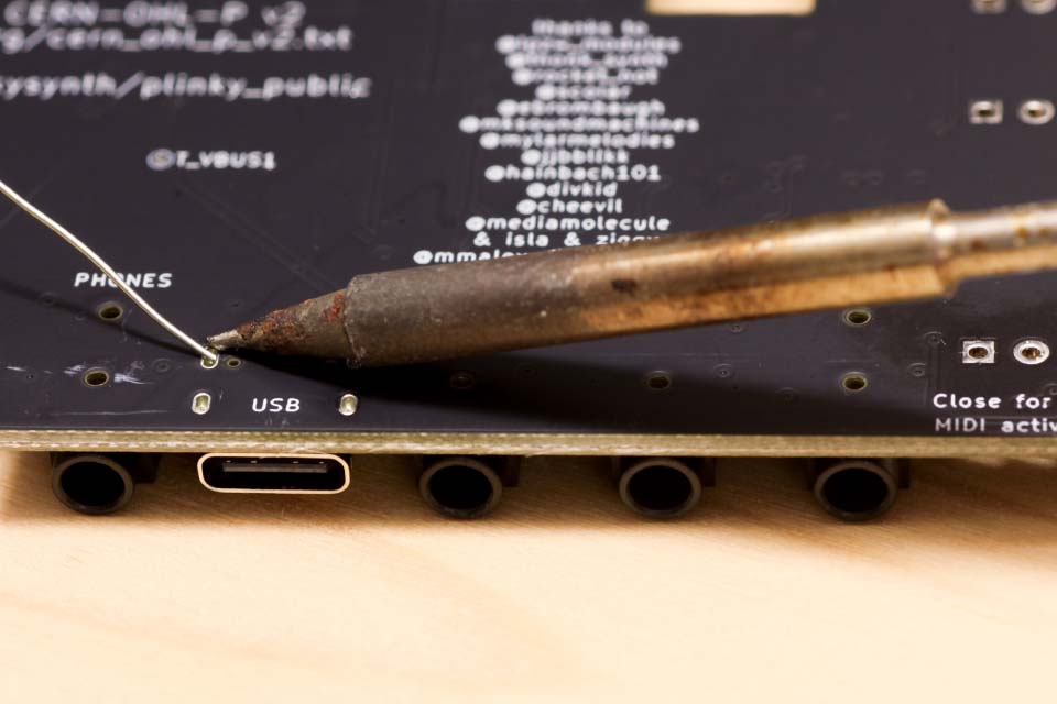
Secure the USB Ports
Solder the through-hole part of the two USB connectors, on the bottom side of the board, between the top and bottom audio jacks. Plinky comes with the USB ports pre-mounted on the top side, and you can reinforce them by soldering from the bottom to secure them firmly to the board. They don’t need a massive amount of solder - just fill up the little holes with a little bit of solder.
Assemble the case
Use the four M3x15mm hex spacers, along with the 8 included M3 screws, to hold Plinky together in a nice pocket operator-style open case.
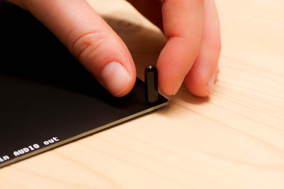
First, screw the spacers into the base plate using the M3 screws and a Philips screwdriver.
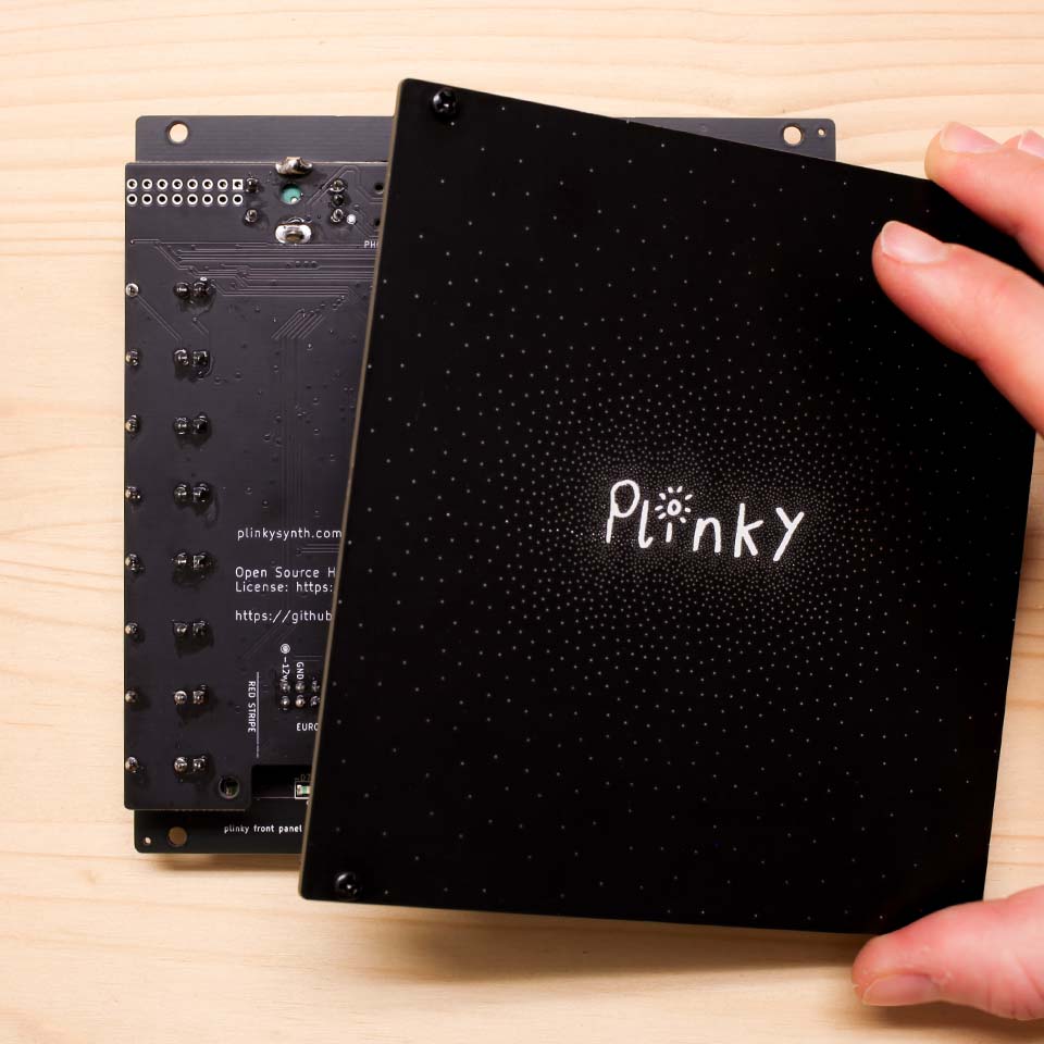
Then, place the back plate with the standoffs and screw Plinky into them from above.

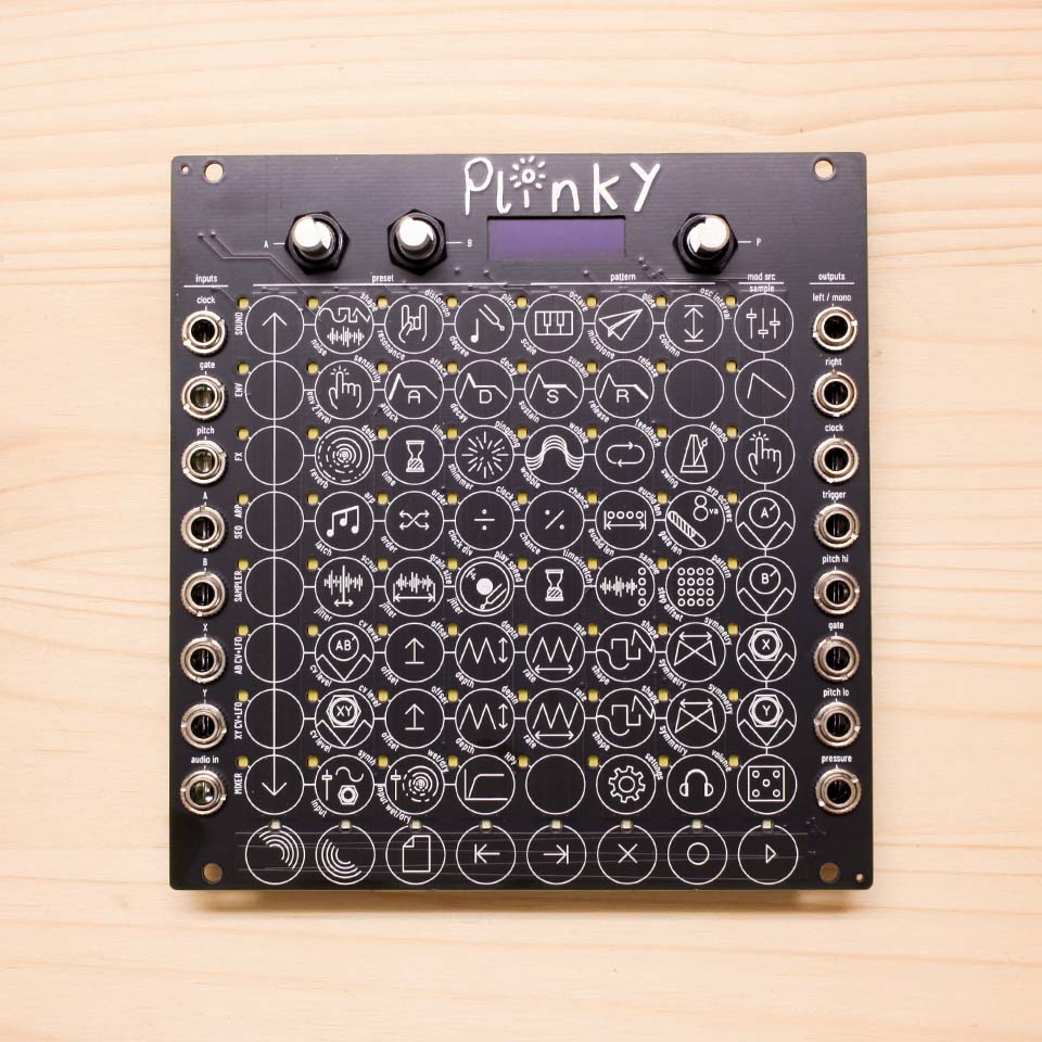
Congratulations, your build is done!
The hardware part is done. Take a moment to appreciate the majesty of your crafting skills.
Now is a good time to stick the 4 included rubber feet to the back plate. They are self-adhesive. Peel them off the wax paper and place them in the four corners of Plinky's back plate, next to the four screws, if you are worried about scratching the surfaces Plinky sits on.
Only once you’ve tested the functionality of your module, put on the aluminium knob caps.
Power up your Plinky
There are three ways to power up your Plinky. Only use one at a time.
- with a USB cable connected to the top port
- or with a USB cable connected to the bottom port
- or using the Europower cable and the Europower header marked Europe
If Plinky shows no sign of powering on at all, power down, and check your soldering carefully for shorts. If it still does nothing, it may be a software issue - work through the Firmware section below, then the Troubleshooting Appendix.
Calibration
Plinky will go into touch calibration mode the first time it boots, or after you finish flashing it with the latest firmware. Calibration mode is indicated on the display, and the bottom row of LEDs light up. You can watch the calibration process in this video.
Touch calibration
In calibration mode, one LED in each column will be lit. Press your finger evenly and as centrally as possible on one of the lit pads, medium hard (mezzo-forte) for a few seconds. After a few seconds, the LED will start blinking and you can release.
Plinky will ask you to do this for all 72 pads, by lighting them in turn.
If you aren’t quite central with your finger, don’t release - just slide your finger into place with it held down, and keep it held down a few seconds once it’s central. If you completely mess up, switch Plinky off and on again, and try again.

Once you’ve finished, your Plinky is ready to play!
You may need to recalibrate Plinky
- if you place Plinky in a new case
- if you power Plinky from Eurorack
- if it is responding offset to your finger presses
- if you buy a previously owned Plinky
Twist the leftmost knob as Plinky powers up, then follow the steps described above.
Calibration will tell you if it finds a short or ‘no connection’ in your pin headers. If this happens, the screen will go white and tell you on which column there is a problem. Keep going with calibration, but take a note of which columns are problematic (counting 1 - 8 from left to right). Then consult the troubleshooting appendix below for help.
Happy Plinking
Congratulations, it is done! Happy Plinking!
Please check out the Play Guide and the Manual.
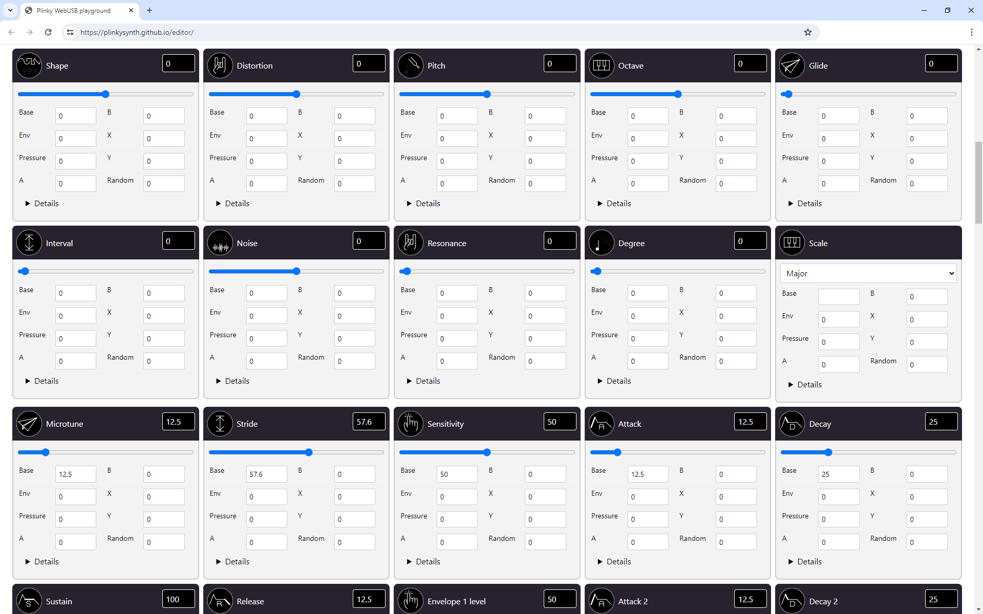
Plinky also has a a browser-based patch editor at plinkysynth.github.io/editor. You will need a Web-Serial enabled browser like Google Chrome to run it, and allow it to connect with Plinky. On Linux, you will need to grant hardware access to Plinky.
Firmware
Plinky V3 ships with firmware 0.A7 or higher.
Install firmware
Here are the steps required to update your firmware to the latest build:
- Download the latest .UF2 file from the Firmware page.
- With Plinky powered off, hold down the encoder (the rightmost knob)
- While still held down, connect Plinky to a PC or Mac USB port
- The screen remains blank, and you’ll see a tunnel of flashing LEDs
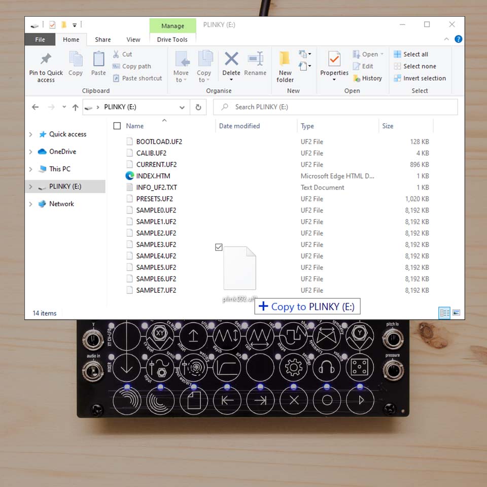
- Plinky should show up on your PC as a USB Drive
- Drag and drop the UF2 file onto the Plinky USB Drive
- The blinking LEDs will change to a flashing pattern
- Once that is done, press the encoder once to reset Plinky

If you run into trouble with updating your build, here are some things you can check:
- If Plinky shows no sign of powering on at all, unplug and check for shorts or bad joints.
- Check that every light is working. If not, you may need to touch up your soldering.
- If you see the tunnel of LEDs, but no USB drive, make sure you use a USB-C cable that you can use to transfer data with.
- Mac M1 / M2 users with OS 14 have reported issues connecting in bootloader mode. You can use the command line to mount Plinky's drive and install UF2 files, follow the instructions below
- Linux users need to follow the instructions here
You can see the update process in this video, at the 46 minute mark.
Install firmware (Mac M1 / OS 14)
In UF2 (tunnel of light) mode, Plinky has been unhappy to automatically mount on some Mac OS versions (14 and higher).
Upgrading to Firmware 0.A7 fixes this issue. To upgrade, mount the drive using the terminal.
- Make sure your USB cable can transmit data
- Plug the USB cable into Plinky.
- Hold the Encoder (rightmost knob) on Plinky.
- With Encoder held, plug the USB cable into your Mac.
- Plinky should come up in UF2 (tunnel of light) mode, with a black screen.
- You can release the encoder.
Open a terminal, and execute
diskutil listPlinky should be listed as a device. It looks like this or similar:
/dev/disk4 (external, physical)
#:     TYPE NAME         SIZE       IDENTIFIER
0:          PLINKY      *100.7 MB   disk4
The disk number is the information you are looking for. Mount Plinky manually via the command line, and adjust the disk number if needed:
sudo mkdir /Volumes/USB
sudo mount -t msdos /dev/disk4 /Volumes/USB
You should see the Plinky drive with the UF2 files. You can now either backup the files to your Mac, or replace them with new firmware or presets.
Install firmware (Linux)
Here are the steps required to update your firmware to the latest build under Linux. This was tested on Raspberry Pi 4 running Raspian.
Upgrading to Firmware 0.A7 fixes the USB drive not mounting automatically. To upgrade, mount the drive using the terminal.
Download the latest UF2 file from the GitHub Repository page. To do this from the command line, open a terminal and enter
wget https://plinkysynth.com/firmware/stable/CURRENT.uf2- With Plinky powered off, hold down the encoder (the rightmost knob)
- While still held down, connect Plinky to a PC or Mac USB port
- The screen remains blank, and you’ll see a tunnel of flashing LEDs
- Mount Plinky as USB Drive from the terminal:
sudo mkdir /mnt/plinky
sudo mount /dev/sda /mnt/plinky
ls /mnt/plinky
You should see the content of Plinky listed as follows:
BOOTLOAD.UF2  CURRENT.UF2  INFO_UF2.TXT  SAMPLE0.UF2  SAMPLE2.UF2  SAMPLE4.UF2  SAMPLE6.UF2
 CALIB.UF2     INDEX.HTM    PRESETS.UF2   SAMPLE1.UF2  SAMPLE3.UF2  SAMPLE5.UF2  SAMPLE7.UF2
Copy the firmware to Plinky.
sudo cp -f CURRENT.uf2 /mnt/plinky/The blinking LEDs will change to a flashing pattern. Once that is done, press the encoder once to reset Plinky.
Browser-based patch editor (Linux)
When trying to connect to the browser-based patch editor using Linux, if you get a message like
SecurityError: Failed to execute 'open' on 'USBDevice': Access denied. you may need to grant hardware access to Plinky. This can be done by adding an udev rule.
First, ensure that the Plinky is connected to your computer via USB.
You can check if the Plinky is connected by running:
lsusbYou should see a line similar to:
Bus 001 Device 026: ID cafe:4018 Plinky PlinkySynth MIDINote the cafe id. If this is not showing up, you may need to check your USB cable.
Next, add yourself to the plugdev group. You can do this by running:
sudo usermod -a -G plugdev $USERYou will need to log out and log back in for the group membership to take effect.
To check if you are in the plugdev group, you can run:
groupsThis should show a list of groups you are in, and plugdev should be one of them.
Next, you need to create a udev rule to allow access to the Plinky.
You can use nano or any other editor of your choice:
sudo nano /etc/udev/rules.d/99-plinky.rulesThe file should have the following line:
SUBSYSTEM=="usb", ATTRS{idVendor}=="cafe", MODE="0660", GROUP="plugdev"This grants read access to the Plinky to the plugdev group.
Then, reload the udev rules:
sudo udevadm control --reload-rulesFinally, unplug and replug the Plinky, and you should be able to connect to the editor.
Thank you to users ddmm64 and ch-one for submitting this solution.
Troubleshooting Appendix
If you bought your board from Thonk, we tested your mainboard and calibrated the CV I/O. We also tested the front panel for defective LEDs.
If you experience problems with Plinky having unlit or stuck LEDs, or not registering touch correctly, please check the Appendix below.
Common hardware issues
So, your Plinky booted up. You probably managed to put new firmware on it, even calibrate it, but during calibration it complained about some of the pads, or now that it’s running, you’ve noticed some LEDs are out or the touch is behaving weird. Don’t worry! These are the most common problems, and they’re easy to fix.
Here are some common problems
Q: I can't get Plinky into flashing mode by pressing down the encoder while plugging in the USB cable.
A: This is the most common question - check that the encoder can actually click! The knobs you received can be of varying height due to manufacturing tolerances, and the encoder needs a little bit of room to click down. You might have to put a tiny paper ball under the knob if you soldered the encoder a little low- this will help keep the knob up and make the encoder click.
Q: Plinky always boots either to ‘calibration’ or play mode, but I can’t get it to boot into the USB update mode (by holding down the encoder on boot)
A: check the solder joints around the encoder. Reflow them, and try again. Be sure to hold the encoder firmly down as you power Plinky up.
Q: Plinky doesnt show up on my PC as USB device when I boot in ‘update mode’. I can see the tunnel of lights, but no USB device shows up.
A: Check your cable. It’s always the cable. Unfortunately, USB cables are a mess. Many are ‘power only’. Plinky needs a cable with 4 wires in it, to carry data. It should be a cable that you can use to transfer data with your phone or other device, for example. Typically, they are slightly fatter and less flexible than the really cheap ‘charging only’ cables. A few people reported raiding their cable boxes for 4 or 5 cables before they found a data cable! Playstation 4 controllers don't use data - they always use bluetooth, even when plugged in. So many playstation controller cables are charging only, and are thus no good.
Q: A whole row of LEDs is unlit.
A: Don’t panic! If it's the blue row at the bottom, it may be that you've tightened the bottom right hex nut tightly and it's ended up crushing a hidden trace and shorting it out. If loosening that hex nut fixes it, then either leave it loose or paint it with varnish to insulate it.
If that nut doesn't fix it, or it's another row, you’ve just got a single dodgy joint on one of the pins of the connectors that go between the front and back panel.
Looking at Plinky with xray eyes from the top (as if you’re playing it), there are two sets of 8x2 pins - one top left, the other top right. The LEDs are on the top right header. The rows of LEDs are controlled by the 8 pins that are on the ‘bottom’ row, as you look at it from above.
In other words, the 8 pins further from the top of the board, on the right side connector. The first pin on the left is the first row of leds. Each pin to the right corresponds to a row of LEDs going down the panel. So if the 6th row down of LEDs is out, you have a dodgy joint on the 6th pin from the left, on the bottom row, of the right connector.
Go check the pins on the back of the mainboard. Check if the socket itself is not damaged.
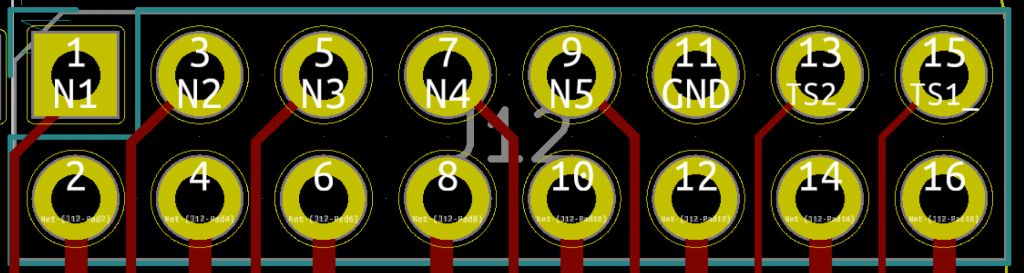
This is the pinout of the right connector for reference.
The first 5 pins at the top correspond to columns of LEDs. The top right 2 pins, marked TS2_ and TS1_, correspond to the touch strip (not LEDs) horizontally at the bottom of Plinky. And the bottom 8 pins, from left to right, correspond to the white LED rows, from top to bottom, as described in the paragraph above.
Bottom line: Row of LED’s out? Check your lower pins on the right connector, and/or try loosening the bottom right nut.
Q: A whole column (or several) of LEDs is unlit
A: Same story as the previous answer - but its one of the top left 5 pins on the right connector, as you look at Plinky from above. Check your joints on the main board, and try again.
Q: Some LEDs are ‘stuck on’
A: You’ve got a short somewhere. Check for excessive solder blobs, or ‘bridges’, or places where two pins have become joined together in your sockets and connectors. Look out, if you put loads of solder on, it can wick under the insulation and make it tricky to see the short. Reflow the joints and poke under the insulation if the short refuses to go. If you have a multimeter, check for dead shorts between pins.
Q: Touch in a particular column is behaving weirdly, perhaps always registering the highest pad, or the lowest, or jumping from one end to the other wildly. Also, calibration probably complained about that column
A: Same story as the LEDs above, but with the LEFT connector. The left connector is all about the main 64 pads touch interface. It is 8 pairs of pins, left to right corresponding to the vertical columns of touch, also left to right. So if the 3rd row from the left is playing up, and doesn’t respond to touch, you’ve got a broken joint or a short circuit on the 3rd pair of pins from the left. Go check your soldering.
After you’ve fixed a touch issue, you’ll need to force Plinky to recalibrate. When you power it up, immediately twist the A knob. This will force Plinky into calibration. It will tell you if it’s happy or sad about particular rows.
Q: Touch in the bottom strip (with blue LEDs) is responding weirdly. Also, calibration probably complained about it (column 9)
A: See the answer to the previous question, however the pins in question are the two rightmost pins in the top row on the RIGHT pin header, looking at Plinky from the top. After fixing, you will need to recalibrate as above.
Q: I have more questions! I need more help!
A: Join our dedicated Discord server. It’s very friendly and we can help with any build issues you may encounter. https://discord.gg/Zf6chA9jAz
CV calibration (optional)
If you’re using your Plinky with other eurorack modules, the pitch inputs and outputs should be ‘factory’ calibrated for 1V / Octave. If you find that it is not tracking correctly across multiple octaves, you can recalibrate the pitch CV jacks using the following procedure. You will need a eurorack cable and either a voltmeter, multimeter, or calibrated eurorack oscillator.
As you power up Plinky, twist the B knob. Plinky will now go into CV calibration mode. Instructions will scroll across the display.
Plug one end of a eurorack cable into the ‘pitch lo’ output on the right side. Clip a voltmeter to the other end - black to the long metal bit of the jack plug, and red to the tip of the plug. Alternatively, you can plug it into a calibrated eurorack oscillator’s Volt/Octave input and use your ears.
Slide your finger up and down on the leftmost column of Plinky, it should cause the voltage (pitch) to go slowly up or down. Adjust it until it is as close to 0v as you can get it (or until it sounds like C0 on your oscillator).
Now touch the second column of Plinky, and it should jump two octaves up - to 2v (C2 on oscillator). Adjust with your finger until it is as close as possible to 2v. You can alternate between the two octaves by pressing the first and second column. Once you are happy it’s a 2 octave gap (2v on the multimeter), move the cable to the pitch hi output on the right, and repeat the 0v and 2v calibration, this time using your finger on the 3rd and 4th columns of Plinky to set the voltages. (1st and 2nd still do ‘pitch lo’, so you can go back any time - just remember to move the cable to the correct output)
Once you’re happy, unplug the cable at the multimeter / oscillator end, and plug it into the ‘pitch in’ socket on the left, forming a loop-back.
Plinky should say ‘Just a mo…!’ while it self-calibrates its pitch CV input, and then it will finally ask you to unplug the cable. Once you’ve done that, it will start up in the normal play mode. Calibration is done!
Recovering from a 'bricked' Plinky
Help! My Plinky is totally dead!
If your Plinky becomes corrupted or ‘bricked’, but there are no electrical faults, and it refuses to even go into the normal ‘flashing’ mode (accessed by holding down the encoder on boot), you can force the software to be completely replaced using ‘DFU’ (Device Firmware Update). This is an emergency procedure, you should not need to do this in normal operation.
You first need to install a DFU flashing program on your computer. I recommend ST Microelectronics’ STM32 Cube Programmer, as they are a somewhat reputable firm, they make the processor chip in Plinky, and their software runs on Mac, Windows and Linux. Unfortunately it requires Java to be installed, but it will guide you through that installation process.
Get STM32 Cube Programmer for free here.
Mac users: use JDK 8u231 from October 2019.
Forcing Plinky into DFU mode
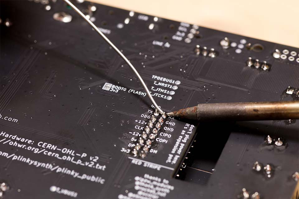
Once the DFU software is installed on your computer, make sure Plinky is unplugged, remove it from its case, then turn it over, and bridge together the 2 little silver pads marked ‘BOOT0’ - using the tips of metal tweezers, a piece of wire, or any small metal object.
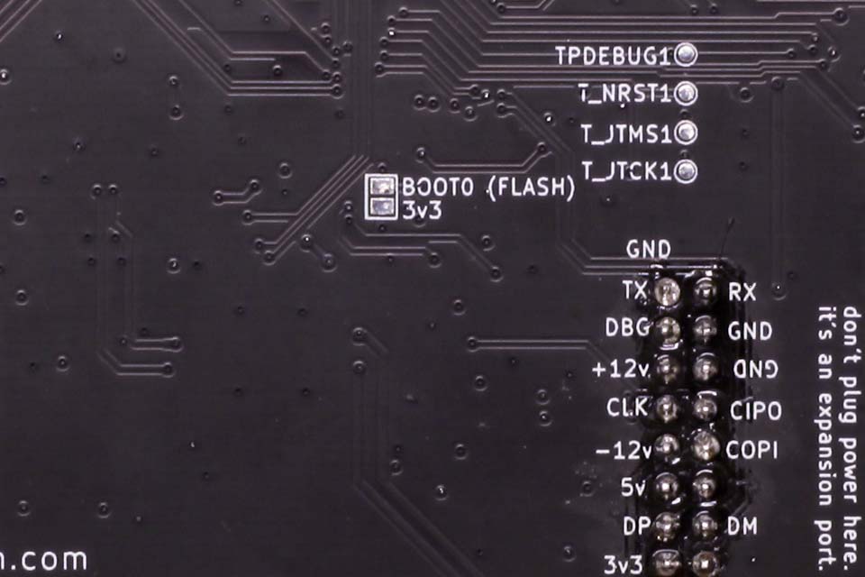
While they are connected, power up Plinky over USB. It can be quite tricky to reliably connect the pads while also powering it up, so it may take a few tries.
If you are successful, the PC should recognise a new USB DFU device. Once detected, you can remove the connection across the pads.
If you cannot get the PC to recognise the DFU device at all, there may be something electrically wrong. Check all your soldering carefully, check for shorts between power lines with a multimeter, and if that still doesn’t help, ask on the Discord server.
Now, run the STM32 Cube Programmer software that you downloaded in the previous step.
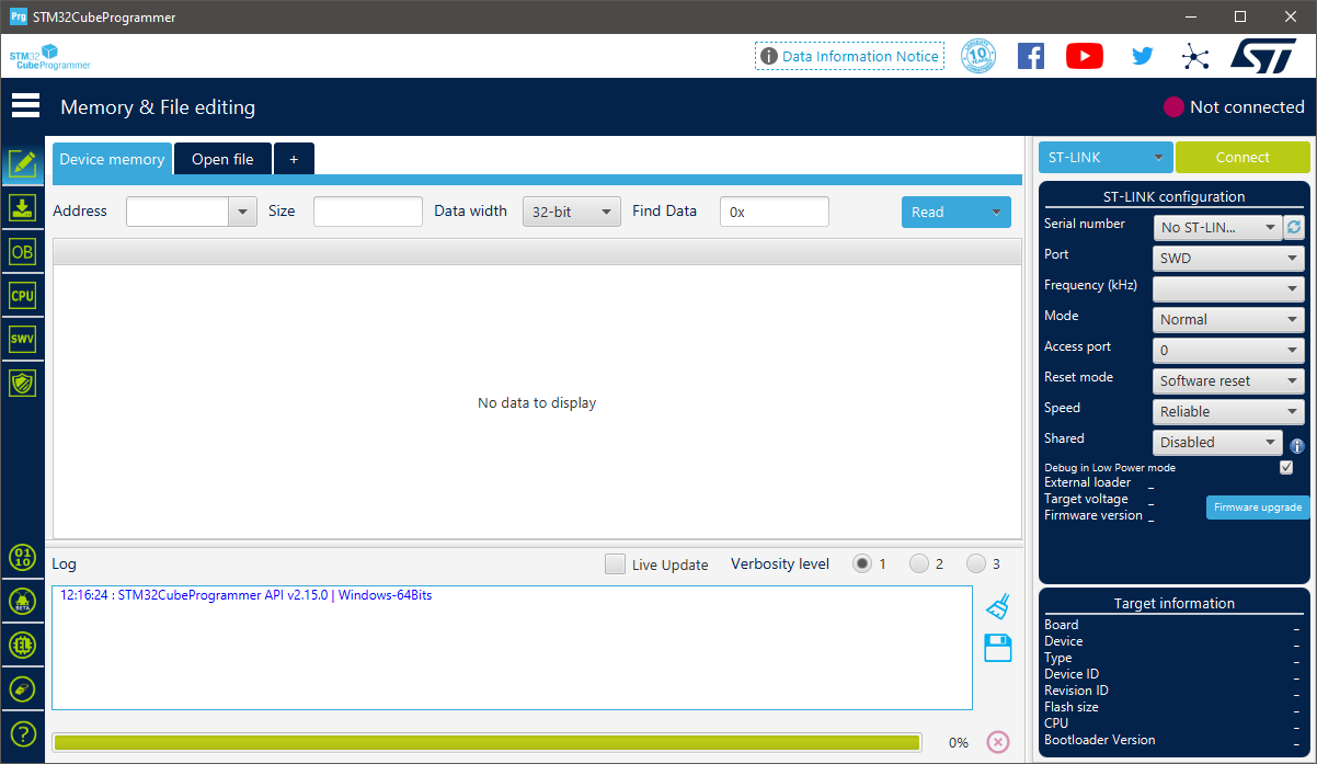
When you run STM32 Cube Programmer, a large window should appear similar to the image here. If the blue box on the top right isn’t saying USB, click on that to change it to USB.
Then click the Open File tab, and select the latest Plinky firmware DFU file.
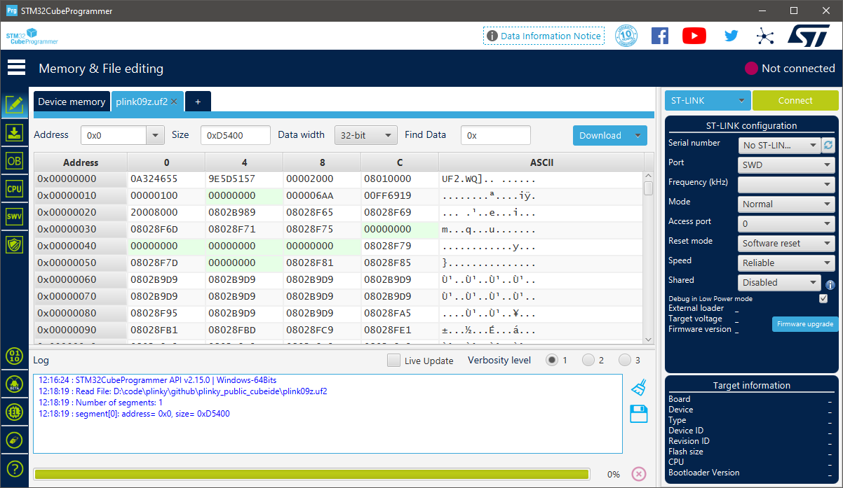
Now you have the Plinky in DFU mode, the PC software you installed should be showing USB1 in the Port drop down. Press the Refresh button on the top right if the port shows No DFU detected. Once detected, it should show a USB Device with a Serial number, like the picture on the right:
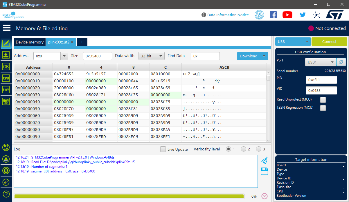
Now click the green Connect button, and then the blue Download button. Wait a few seconds, and it should program. Once it’s done, press Disconnect, and you can unplug your Plinky. Don’t rush. If you unplug mid-program, you may find that you have to repeat this whole process.
Safety Instructions
In Compliance with GPSR EU Regulation 2023/988, find the Safety Instructions here.